This post I am going to present my work on developing the base code for a differential drive mobile robot base. The code will be coded to work with Arduino where we are going to use C language. Let’s start with the picture below where, the mobile robot has two wheel each wheel rotates independently. There size of the robot is known so we have the distance between the center of the wheel which is call w and the wheel radios is \(R\). Each wheel has velocity which is \(v_l\) and \(v_r\) for the left and right wheel respectively. Using these information we can write the model equation for the velocity we get the following equations
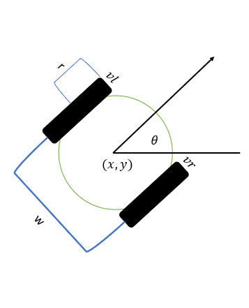
However, the standard control of mobile base is velocity \(v\) and angular velocity \(\omega\); therefore, we need to convert this input. Using a dynamic model of bicycle which is shown in the figure below we get the three equations
$$\dot x = v*cos{\theta} -(4)$$ $$\dot y = v*sin{\theta} -(5)$$ $$\dot \theta = \omega -(6)$$ Now we can solve the first three equation by substitute \(\dot x, \dot y, \dot\theta\) we get the following equations $$\frac {2v} R = v_r + v_l -(7)$$ $$\frac {2v} R = v_r + v_l -(8)$$ $$\frac{\theta w} R = v_r + v_l -(9)$$Now we solve equation 8 and 9 by subtract 8 of 9 and one more time by adding 8 to 9, therefore we will get:
$$V_l = \frac{2v - \omega l}{2R} -(10)$$ $$V_r = \frac{2v + \omega l}{2R} -(11)$$ OdometrySo far, we map the input \(v\) and \(\omega\) to differential drive mobile base in order to get the velocity in \(\dot x , \dot y , \dot \theta\). Now we need to track the position of the base (state [x,y,\theta]) in relative to the world. We will use encoder to measure the distance move. Looking for the figure below we see there are three arcs that the robot generate during movement which is \(D_l\, D_r and D_c\) for the movement of left wheel, right wheel and center of base respectively. The center distance is computed by taking the sum of left and right distance divided by two equations below
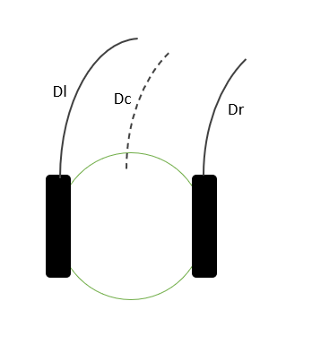
And to compute \(D_r\) and \(D_l\)
$$D_r = 2 \ pi R \frac{\Delta tick_r} N -(13)$$ $$D_l = 2 \ pi R \frac{\Delta tick_l} N -(14)$$ Where N is the number of ticks in one revolution. Now to compute the state of the robot we use the following equations $$x^{'} = x + D_c + cos\theta -(15)$$ $$y^{'} = y + D_c + sin\theta -(16)$$ $$\theta^{'} = \theta + \frac{D_r - D_l}w -(17)$$ PID controllerTo control the speed of the wheel we need to apply a PID controller to control the velocity of the wheel. Figure below shows the implementation where the input velocity \(v_i\) where \(i=[r,l]\) the PID compute the output PWM to control the motor.
Arduino CodeAbove we present the mathematical model of the base where we have a two input to control the base and we get the output state of the base \(x=[x,y,\theta]\). First we include the PID library then we define the pins used to control the motor and read encoder.
// include libraries
#include <PID_v1.h>
// Define the encoder pins
#define leftEncoderPinA 2
#define leftEncoderPinB 4
#define rightEncoderPinA 3
#define rightEncoderPinB 5
#define leftSpeedPin 6
#define rightSpeedPin 9
#define leftDir1 7
#define leftDir2 8
#define rightDir1 10
#define rightDir2 11
Here I define the speed of the loop in the main function this will help us to get the updated state at fixed rate.
// define the speed of the loop
unsigned long currentMillis;
long previousMillis = 0;    // set up timers
int LoopSpeed = 30; // 30Hz
float deltaTime = 0;
Now I define the PID controller parameters and set the PID, note that these value need to tuned according to the need.
// pid parameters:-
double leftSetpoint , leftCurrentVelocity , leftOutput;
double rightSetpoint,rightCurrentVelocity,rightOutput;
double Kp=0.00206812507453938;
double Ki=0.0339782106923304;
double Kd=3.14697363162208e-05;
// define object :-
PID leftWheelPID(&leftCurrentVelocity, &leftOutput, &leftSetpoint,Kp,Ki,Kd,DIRECT);
PID rightWheelPID(&rightCurrentVelocity, &rightOutput, &rightSetpoint,Kp,Ki,Kd,DIRECT);
Here I define the base parameters and measurement such as wheel size and distance between wheels
// All parameter should be in meter
#define WHEEL_DIAMETER 0.1254
#define WHEEL_SEPRATION 0.418
#define ENCODER_TICK_PERREVOLUTION 72
#define pi 3.14159265359
Now I define the variables used to track the left and right wheel, and I define the target velocity and angulare velocity \(v\) and \(\omega\).
// define the gloable parameters
volatile int leftTick = 0; // universal count
volatile int rightTick = 0; // universal count
volatile int leftTickOld = 0; // universal count
volatile int rightTickOld = 0; // universal count
double targetVelocity;
double trargetAngularVelocity;
Here I create structures for wheel velocity and the robot state to simplify in creating function late.
// This structure use to return the left and the right velocity of the wheels
struct WheelsVelocity{
  double leftVelocity;
  double rightVelocity;
};
struct Coordinate{
  float x;
  float y;
  float theta;
};
Now I create the function that convert the input velocity and angular velocity and generate a separate velocity for the left and wright wheel.
// This function use to compute the turning velocity for each wheel
// velocity : is the required speed to move
// angularVelocity: is the rotating speed
// the return is the speed of the left and right wheel turning
struct WheelsVelocity GetWheelVelocity(float baseVelocity, double angularVelocity){
  WheelsVelocity velocity;
  velocity.leftVelocity = (2*baseVelocity + angularVelocity*WHEEL_SEPRATION)/WHEEL_DIAMETER;
  velocity.rightVelocity = (2*baseVelocity - angularVelocity*WHEEL_SEPRATION)/WHEEL_DIAMETER;
  return velocity;
}
This function return the state of the robot by passing the encoder reading
//This function use to compute the coordinate of the base
void GetCordinate(double leftTick, double rightTick, struct Coordinate *currentPosition){
  double leftDeltaTick = leftTick - leftTickOld;
  double rightDeltaTick = rightTick - rightTickOld;
  // assigne the current encoder value to old encoder value
  leftTickOld = leftTick;
  rightTickOld = rightTick;
  double leftDistance = pi * WHEEL_DIAMETER* (leftDeltaTick/ENCODER_TICK_PERREVOLUTION);
  double rightDistance = pi * WHEEL_DIAMETER* (rightDeltaTick/ENCODER_TICK_PERREVOLUTION);
  double centerDistance = (leftDistance + rightDistance) / WHEEL_SEPRATION;
  currentPosition->x = currentPosition->x + centerDistance*cos(currentPosition->theta);
  currentPosition->y = currentPosition->y + centerDistance*sin(currentPosition->theta);
  currentPosition->theta = currentPosition->theta + ((leftDistance - rightDistance) / WHEEL_SEPRATION);
}
Now we define the setup function and define the pins
void setup() {
  //------- Setup encoder pins
  pinMode(leftEncoderPinA , INPUT);
  pinMode(leftEncoderPinB , INPUT);
  pinMode(rightEncoderPinA , INPUT);
  pinMode(rightEncoderPinB , INPUT);
  // interrupt 0 digital pin 2 positive edge trigger
  attachInterrupt(0, LeftFlag, RISING);
  // interrupt 1 digital pin 3 positive edge trigger
  attachInterrupt(1, RightFlag, RISING);

  //------- Setup Motor pin to output
  pinMode(leftDir1, OUTPUT);
  pinMode(leftDir2, OUTPUT);
  pinMode(leftSpeedPin, OUTPUT);

  pinMode(rightDir1, OUTPUT);
  pinMode(rightDir2, OUTPUT);
  pinMode(rightSpeedPin, OUTPUT);

  //------- Setup PID and initialize
  rightWheelPID.SetMode(AUTOMATIC); //start calculation.
  rightWheelPID.SetOutputLimits(-255,255);
  rightWheelPID.SetSampleTime(LoopSpeed);

  leftWheelPID.SetMode(AUTOMATIC); //start calculation.
  leftWheelPID.SetOutputLimits(-255,255);
  leftWheelPID.SetSampleTime(LoopSpeed);
  leftSetpoint=0;
  rightSetpoint=0;
  // start serial port at 9600 bps:
  Serial.begin(9600);
}
The below code is the main loop of the base. Here we set the loop to work at 30Hz. The input take from the serial port.
void loop() {
currentMillis = millis();
if (currentMillis - previousMillis >= LoopSpeed) { // start timed event
deltaTime = (currentMillis - previousMillis)/1000; // divided by 1000 to be in second
previousMillis = currentMillis;
//-------step 1: Read serials for incoming data (a velocity angular_velocity)
if (Serial.available() > 0){
// this to make sure that we are reading the correct value
if (Serial.read() == 'c'){
targetVelocity = Serial.parseFloat();
trargetAngularVelocity = Serial.parseFloat();
}
}
//-------step 2: compute the velocity of the left and right wheel
struct WheelsVelocity targetWheelsVelocity= GetWheelVelocity(targetVelocity, trargetAngularVelocity);
//-------step 3: apply PID controller to get the PWM
// To acces the velocity of each wheel use the follow
//targetWheelsVelocity.leftVelocity;
//targetWheelsVelocity.rightVelocity;
leftSetpoint = targetWheelsVelocity.leftVelocity;
rightSetpoint = targetWheelsVelocity.rightVelocity;
leftCurrentVelocity = Get_speed(leftTick, leftTickOld, deltaTime);
rightCurrentVelocity = Get_speed(rightTick, rightTickOld, deltaTime);
rightWheelPID.Compute();
leftWheelPID.Compute();
//-------step 4: move the motors
int leftWheelPWM = leftOutput;
int rightWheelPWM = rightOutput;
MoveMotor(leftDir1, leftDir2,leftSpeedPin, leftWheelPWM );
MoveMotor(rightDir1, rightDir2,rightSpeedPin, rightWheelPWM );
debugPID();
//-------step 5: update the coordinate of the base
struct Coordinate currentPosition;
GetCordinate(leftTick, rightTick, ¤tPosition);
//-------step 6: publish these cooridnate
Serial.print(currentPosition.x);
Serial.print(currentPosition.y);
Serial.print(currentPosition.theta);
Serial.print('\n');
Serial.println(leftTick);
}
}These functions used to control the motors
void MoveMotor( int dirictionPin1, int directionPin2, int PWMPin, int PWMValue){
  if (PWMValue > 0){
    digitalWrite(dirictionPin1,HIGH);
    digitalWrite(directionPin2,LOW);
  }else{
    digitalWrite(dirictionPin1,LOW);
    digitalWrite(directionPin2,HIGH);
  }
  analogWrite(PWMPin,PWMValue);
}
The help functions of encoder reading and one function to control the motor speed.
void LeftFlag() {
  // add 1 to count for CW
  if (!digitalRead( leftEncoderPinB )) {
    leftTick ++ ;
  }
  // subtract 1 from count for CCW
  if (digitalRead( leftEncoderPinB )) {
    leftTick --;
  }
}

void RightFlag() {
  // add 1 to count for CW
  if (!digitalRead( rightEncoderPinB )) {
    leftTick ++ ;
  }
  // subtract 1 from count for CCW
  if (digitalRead( rightEncoderPinB )) {
    leftTick --;
  }
}

float Get_speed(int tick, int oldTick, int time){
    // make sure the time is in second so we divided by 60 to get in minutes
    float rpm = (tick-oldTick)/(time/60);
    return rpm;
}